| |
  |
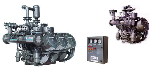
| Power Saver Refrigeration Compressors |
 |
|
 |
|
APPLICATIONS
SUPERFREEZE SRA-Series Heavy Duty Refrigeration Compressors cover a wide range of duties from high to low temperature in general applications such as cold storage, quick freezing, ice-making and air-conditioning. Additionally, they are particularly suitable for special applications in breweries, steel works, and chemical and research establishments.
SPECIFICATIONS
`SRA-Series' compressors are well designed and robust machines capable of running continuously for prolonged periods with the minimum of attention. They are suitable for all normal applications and operating conditions.
COMPRESSORS’ COMPONENTS
CRANKCASE AND CYLINDER HOUSING - These are iron /steel bodies. Easy access to the interior of the compressor for inspection, cleaning or adjustment of motion work can be gained by removing the back.-end cover, or a single hand hole cover provided for this purpose. All models are fitted with an, oil level sight glass and drain plug.
CRANKSHAFT - The two- throw type cranskshaft is forged of special alloy steel, accurately machined and with fine ground finish bearing surfaces. The shaft is dynamically balanced to minimise vibration. It is carried on two wrapped bimetallic bushes within the crankcase. When necessary this type of bearing can easily be replaced. Crankshaft thrust washers are fitted to one end of the crankcase. These are also easily renewable.
CRANKSHAFT GLAND SEAL - The cranskshaft is gas sealed at the gland end by a flexible multi spring precision seal, which is continuously lubricated and cooled by oil from the pressure feed system while the compressor is running. The Sealing faces are Tungston carbide and Bronze.
CYLINDER LINERS-The liners are of high tensile cast iron with a fine ground external and honed internal finish.
CONNECTING RODS-The connecting rods are H section steel stampings fitted with slip-in steel backed white-metal lined bigend bearings, and bronze small end bushes.
PISTONS-The pistons are made of an aluminium alloy. They are fitted with 3 compression and 2 oil scraper rings to provide efficient gas sealing and good oil control.
VALVES - The ring plate type suction and delivery valves are made of special alloy steel. The suction valve is arranged to seat on the flanged head of the cylinder liner. The delivery valve and seat form part of the safety head assembly. Both valves are spring loaded for positive action.
SAFETY HEAD - The saftey head in each cylinder is held down by a heavy coil spring against which it can lift to relieve undue pressure.
GAS STRAINER - The gas strainer is conveniently housed on the suction connection of the machine and can be removed for cleaning without difficulty. A felt filter in provided for fitting inside the strainers during the compressors running-in period to trap scale and other impurities scoured from the system by the refrigerant.
DELIVERY MANIFOLD - The delivery manifold is a common header into which gas from the several cylinders is discharged. The manifold is so designed to prevent the minimum heat exchange surface between suction and delivery gas passages. This feature assumes importance when the machine is used as an ammonia compressor.
LUBRICATION - Oil under pressure is supplied to all bearings and the crankshaft seal by means of a gear pump driven directly from the end of the cranskshaft. Oil in the sump is drawn into the pump suction through a fine mesh strainer and delivered to the bearings by way of a `felt element' oil filter. A magnet is also provided to trap any magnetic particles. A crank case oil level sight glass is fitted. Oil contained in the refrigerant returning to the compressor suction is separated from the gas in a low velocity suction chamber. This oil drains back into the sump Chamber which allows the crankcase to vent but prevents loss of oil. The compressor is protected against oil failure by a differential oil switch, which causes the compressor to stop should the pressure fall below a predetermined minimum.
UNLOADING EQUIPMENT-(Oil operated) Manual or automatic unloading equipment built into the cylinders are provided to give light load start and capacity reduction, or light load start only. Loading or unloading of the cylinders is achieved by a hydraulic mechanical suction valve lifting mechanism on each individual cylinder. For unloading the suction valve ring is lifted from its seat in the cylinder collar by spring tension. Loading of cylinder is affected by admitting control oil pressure to the control Piston allowing the suction valve ring to descend on its seat.
CYLINDER HEAD COOLING - Compressors operating on ammonia refrigerant are fitted with cylinder heads and covers suitable for water cooling.
SPECIAL ACCESSORIES
-
Drive set comprising of V-belt, motor pulley and flywheel, for a wide range of speeds.
-
Bare components-Base frame for compressor with foundation bolts.
-
Shut-off valves for suction and discharge lines.
-
Electrically operated solenoid valves for capacity control.
-
Pressure gauges, safety pressure cut-out, oil safety cut-off with or without mounting panel.
-
Crankcase heater and oil separator.
-
Equaliser connections for parallel operating compressors.
-
Interstage cooling systems to suit two stage compressors.
-
Built-in cooling water manifold.
-
Special oil separators, combined base frames for compressor and motor for marine applications.
FINISH ON COMPRESSORS
Chemically degreased. Three coats of paint applied, two undercoats and a finishing coat.
TESTS
After machining, each crankcase and cylinder body is subjected to hydraulic and submerged air pressure tests. When assembled each machine is given a free air running test and capacity evaluation tests as per standards. |
|
|
NH3
(Single Stage)
Capacity Rating *
Compressor
Model |
S.S.T.
(oC) |
Kcal/hr.
SDT (+40oC) |
Kcal/hr.
SDT (+45oC) |
KW
SDT (+40oC) |
KW
SDT (+45oC) |
SRA -20 |
+ 10
+ 5
0
- 5
- 10
- 15 |
1,12,800
93,100
78,880
60,925
48,020
36,920 |
1,07,815
89,920
71,800
57,080
44,620
33,975 |
22.1
21.4
20.6
19.2
17.2
15.7 |
25.1
24.1
22.5
20.7
18.6
16.6 |
SRA -100 |
+ 10
+ 5
0
- 5
- 10
- 15 |
1,41,850
1,16,900
94,950
76,250
59,950
43,650 |
1,36,400
1,11,950
90,500
72,200
-
- |
27.0
26.4
25.4
24.0
22.1
20.4 |
30.2
29.2
27.7
25.8
-
- |
SRA -200 |
+ 10
+ 5
0
- 5
- 10
- 15 |
2,83,700
2,33,800
1,89,900
1,52,500
1,19,900
87,300 |
2,72,800
2,23,900
1,81,000
1,44,400
-
- |
53.0
51.8
49.8
47.0
43.3
40.0 |
59.3
57.3
54.4
50.6
-
- |
SRA -300 |
+ 10
+ 5
0
- 5
- 10
- 15 |
4,25,600
3,50,700
2,84,900
2,28,700
1,79,900
1,31,100 |
4,09,200
3,35,900
2,71,600
2,16,600
-
- |
78.5
76.7
73.8
69.6
63.9
60.0 |
87.9
85.0
80.7
74.9
-
- |
SRA -400 |
+ 10
+ 5
0
- 5
- 10
- 15 |
5,67,600
4,67,600
3,79,900
3,05,000
2,39,800
1,74,600 |
5,45,600
4,47,900
3,62,100
2,88,800
-
- |
104.1
101.6
97.7
92
84.6
79.3 |
116.6
112.6
106.9
99.2
-
- |
SRA -600 |
+ 10
+ 5
0
- 5
- 10
- 15 |
8,51,300
7,01,500
5,69,900
4,57,500
3,59,800
2,62,200 |
8,18,500
6,71,900
5,43,200
4,33,300
-
- |
155.0
151.3
143.4
137.0
125.8
118.2 |
173.8
167.8
159.2
147.7
-
- |
SRA -900 |
+ 10
+ 5
0
- 5
- 10
- 15 |
12,77,000
10,52,300
8,54,800
6,86,300
5,39,700
3,93,300 |
12,27,700
10,07,900
8,14,900
6,50,000
-
- |
231.4
226.0
217.1
204.5
187.6
168.6 |
259.6
250.7
237.8
220.5
-
- |
|
* Basis for capacity Ratings
SDT : 40°c and 45°c Superheat : 5°c
Capacities at 1000 RPM, 3020 k.Cal = 12000 BTU = 1TR, Effective at shaft in KW |
|
NH3
Double Stage
Capacity Rating * |
Compressor
Model |
S.S.T.
(oC) |
Kcal/hr.
SDT (+40oC) |
KCal/hr.
SDT (+45oC) |
KW
SDT (+40oC) |
KW
SDT (+45oC) |
SRA -201 |
- 15
- 20
- 25
- 30 |
1,12,500
90,900
71,100
54,900 |
1,09,600
88,500
69,200
- |
46.5
42.5
38.2
34.0 |
49.8
45.5
40.8
- |
SRA -301 |
- 25
- 30
- 35 |
1,01,700
78500
59,900 |
98,900
76,300
- |
53.2
47.1
41.4 |
56.5
49.9
- |
SRA -402 |
- 15
- 20
- 25
- 30 |
2,25,000
1,81,800
1,42,200
1,09,800 |
2,19,300
1,77,100
1,38,400
- |
90.8
82.9
74.4
65.9 |
97.5
88.8
79.4
- |
SRA -501 |
- 35
- 40
- 45 |
90,900
68,400
50,500 |
82,200
66,300
- |
62.7
54.0
46.0 |
65.9
56.7
- |
SRA -603 |
- 15
- 20
- 25
- 30 |
3,37,600
2,72,800
2,13,300
1,64,700 |
3,29,000
2,66,700
2,07,700
- |
135.2
123.3
110.5
97.9 |
145.3
132.2
118.1
- |
SRA -702 |
- 30
- 35
- 40 |
1,78,900
1,36,500
1,02,700 |
3,29,000
1,32,600
- |
104.9
91.7
75.0 |
112.2
96.9
- |
|
* Basis for capacity Ratings
SDT : 40°c and 45°c Superheat : 5°c
Capacities at 1000 RPM, 3020 k.Cal = 12000 BTU = 1TR, Effective at shaft in KW |
|
R-22
Single Stage
Capacity Rating * |
Compressor
Model |
S.S.T.
(oC) |
Kcal/hr.
SDT (+40oC) |
Kcal/hr.
SDT (+45oC) |
KW
SDT (+40oC) |
KW
SDT (+45oC) |
SRA -20 |
+ 10
+ 5
0
- 5
- 10
- 15
- 20
- 25 |
90,800
75,810
62,900
51,450
41,650
33,110
25,820
19,160 |
85,800
71,440
58,950
48,100
38,750
30,615
23,750
17,285 |
34,2
32.5
30.8
28.6
26.1
23.5
20.7
17.8 |
36.7
34.9
33.2
29.9
27.1
24.0
20.9
17.9 |
SRA -200 |
+ 5
0
- 5
- 10
- 15
- 20
- 25
- 30 |
2,04,300
1,69,500
1,39,000
1,12,500
89,600
69,900
53,000
38,700 |
1,92,900
1,59,400
1,30,200
1,04,800
82,900
64,000
47,800
34,100 |
55.3
52.7
49.8
46.6
43.0
38.7
33.6
27.5 |
59.7
56.7
53.3
49.5
45.1
39.9
33.6
26.0 |
SRA -300 |
+ 5
0
- 5
- 10
- 15
- 20
- 25
- 30 |
3,06,400
2,54,200
2,08,500
1,68,800
1,34,500
1,04,900
79,600
58,100 |
2,89,300
2,39,200
1,95,300
1,57,300
1,24,300
96,000
71,800
51,200 |
82.0
78.0
73.7
69.0
63.5
57.1
49.5
40.2 |
88.6
84.0
79.0
73.2
66.5
58.8
49.4
38.0 |
SRA -400 |
+ 5
0
- 5
- 10
- 15
- 20
- 25
- 30 |
4,08,600
3,39,000
2,78,000
2,25,100
1,79,300
1,39,900
1,06,100
77,500 |
3,85,800
3,18,900
2,60,400
2,09,700
1,65,800
1,28,100
95,700
68,300 |
108.6
103.4
97.7
91.3
84.0
75.4
65.3
52.9 |
117.5
111.4
104.6
97.0
88.2
77.7
65.2
50.0 |
SRA -600 |
+ 5
0
- 5
- 10
- 15
- 20
- 25
-30 |
6,12,900
5,08,500
4,17,100
3,37,700
2,69,000
2,09,900
1,59,200
1,16,300 |
5,78,700
4,78,400
3,90,700
3,14,600
2,48,700
1,92,100
1,43,600
1,02,500 |
161.8
154.0
145.4
135.8
124.9
112.1
96.8
78.3 |
175.1
166.0
155.8
144.4
131.1
115.5
96.7
73.9 |
SRA -900 |
+ 5
0
- 5
- 10
- 15
- 20
- 25
- 30 |
9,19,200
7,62,600
6,25,500
5,06,400
4,03,500
3,14,700
2,38,800
1,74,300 |
8,67,900
7,17,600
5,85,900
4,71,900
3,72,900
2,88,000
2,15,400
1,53,600 |
242.5
230.7
218.0
204.1
187.8
168.9
146.4
118.9 |
262.6
249.0
234.2
217.0
197.1
174.3
146.4
112.1 |
|
* Basis for capacity Ratings
SDT : 40°c and 45°c Superheat : 5°c
Capacities at 1000 RPM, 3020 k.Cal = 12000 BTU = 1TR, Effective at shaft in KW |
|
|
|
TECHNICAL
DATA FOR
SINGLE-STAGE COMPRESSORS |
Compressor Model
Cylinder arrangement
Number of cylinders
Bore & Stroke (mm)
Suction (mm)
Discharge (mm)
Swept volume of
Suction gas Cu.m/hr
At 1000 RPM
Max. Speed (RPM)
Min. Speed (RPM) |
SRA-20
Vertical
2
110x85
50
40
96.9
1500
600 |
SRA-100
Vertical
1
160x110
50
40
132.7
1000
400 |
SRA-200
1 x V
2
160x110
65
50
265.4
1000
400 |
SRA-300
1 x W
3
160x110
80
50
398.1
1000
400 |
SRA-400
2 x V
4
160x110
80
80
530.8
1000
400 |
SRA-600
2 x W
6
160x110
100
80
796.2
1000
400 |
SRA-900
3 x W
9
160x110
125
100
1194.3
1000
400 |
| Direction of Rotation |
Anticlock-wise when
viewed from shaft end |
| Fly Wheel Diameter |
420MM
(16 ½) |
686MM.(27") |
| Max. Discharge Pressure |
21 bar |
|
TECHNICAL
DATA FOR
DOUBLE-STAGE COMPRESSORS |
Compressor Model
Cylinder arrangement
Number of cylinders in LP
Number of cylinders in HP
Bore & Stroke (mm)
Suction (mm)
Discharge (mm)
Swept volume of
Suction gas Cu.m/hr
At 1000 RPM
Max. Speed (RPM)
Min. Speed (RPM) |
SRA-201
1 x W
2
1
160x110
65
50
265.4
1000
750 |
SRA-301
2 x V
3
1
160x110
80
50
398.1
1000
750 |
SRA-402
2 x W
4
2
160x110
100
50
530.8
1000
750 |
SRA-501
2 x W
5
1
160x110
100
50
663.5
1000
750 |
SRA-603
3 x W
6
3
160x110
100
50
796.2
1000
750 |
SRA-702
3 x W
7
2
160x110
100
50
928.9
1000
750 |
|
| Direction of Rotation |
Anticlock-wise when
viewed from shaft end |
| Fly Wheel Diameter |
686MM.(27") |
| Max. Discharge Pressure |
21 bar |
|
|
|
|
 |
|
|
